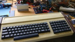
After a visual check of the keyboards (see this post), I had a couple of questions, which were do the keyboards work? and how do the keyboards work?
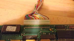
On the basis that neither of the Alphameric had their EPROM windows covered, and that one of the Cherry keyboards had already been modified, I chose the other Cherry one as the most likely to work. After opening it up (again), I checked the 20 pin header. It was quite easy to find out what the 5v and Ground pins were (traceable to the power pins on the logic chips and corresponds to red and black wires on pin 1 & 2!), but the others were going to need something more to diagnose
Time to break out the oscilloscope! It didn’t take long to discover that the pins 3-9 changed upon pressing a key. Curiously, they didn’t didn’t change when releasing the key though. Also, depending on which key was pressed, they might not change at all. Pin 9 was most likely to change and pin 3 was least likely to change.
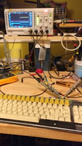
So, there we have a 7 bit ASCII pattern! The value was being latched, and pin 11 was a pulse to indicate that a valid signal was ready to be read.
For last years Retro Challenge Andy Collins had done pretty much the same but opposite thing, where he had a faulty Alphameric keyboard that he replaced with an Arduino & USB keyboard. The timing diagram was particularly useful, so thanks Andy!
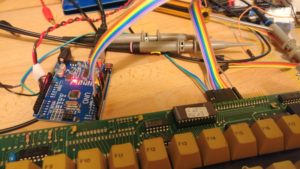
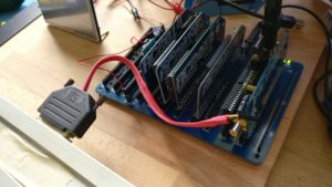
If an Arduino can be used to simulate being a keyboard, then it can also be used to read one! So I plugged in a cheap Uno that I had lying around and wrote a quick sketch to read the data pins D0 – D6 every time the strobe pin goes high, then convert this in to an ASCII number and print the character on the serial port. I also got it to print out the ASCII code itself, which was handy for working out what keys had non-printable characters
The regular keys A-Z were affected by the two modifier keys to give 3 different characters (a, A and ASCII 1, or b, B and ASCII 2 etc.). The Del key was the only other one to have 2 modified outputs, but most of the others had just one output regardless of the shift or control key being pushed.
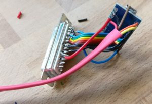
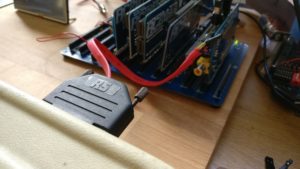
I had a spare Arduino Mini Pro clone lying around and also a 25 pin D socket, so I figured it might be handy to make up a slightly more permanent adaptor that will plug in to the keyboard. Some of the soldering is a bit dodgy here, but it’s all solid enough :-)
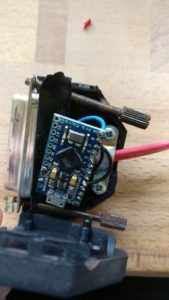
Also, the important thing is that it all fits inside the 25 pin D shell!
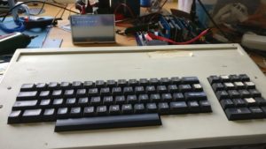
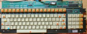
The Cherry keyboard worked exactly as expected, and allows me to use it with my RC2014! However, I wanted to know if the other, Alphameric keyboards would work too.
They had the same connection, although I hadn’t done any of the diagnostic work that I did with the Cherry one – but it was worth taking a chance. And it turns out that yes, they work too! Well, the regular Alphameric keyboard works exactly as the Cherry one does!
The one with the hex keyboard, though, only partially works. The main keyboard section works as expected, however, the hex keypad sends out odd key codes. Some of them output several characters, and can even put the RC2014 or the Arduino adaptor in to a weird mode that means the main keyboard types weird stuff until it is reset. Not sure if this is something to do with bit corruption in the EPROM, or some other kind of error, or if it’s actually by design – however, that’s for diagnosis another time. There’s still lots more stuff I need to go through yet and time is ticking away…
Arduino Code
#define Strobe 9
#define DATA0 8
#define DATA1 7
#define DATA2 6
#define DATA3 5
#define DATA4 4
#define DATA5 3
#define DATA6 2

int DATABYTE = 0;

void setup() {
  pinMode(DATA0, INPUT);
  pinMode(DATA1, INPUT);
  pinMode(DATA2, INPUT);
  pinMode(DATA3, INPUT);
  pinMode(DATA4, INPUT);
  pinMode(DATA5, INPUT);
  pinMode(DATA6, INPUT);
  pinMode(Strobe, INPUT);
  digitalWrite (Strobe, HIGH);
  Serial1.begin(115200);
  //Serial.println ("Started");
}

void loop() {
int pulse = digitalRead(Strobe);
  if (pulse == 0 ) {
    printASCII();
  }
}

void printASCII() {
  delay (1);
  DATABYTE = ((digitalRead(DATA0)) + (digitalRead(DATA1) * 2) + (digitalRead(DATA2) * 4) + (digitalRead(DATA3) * 8) + (digitalRead(DATA4) * 16) + (digitalRead(DATA5) * 32) + (digitalRead(DATA6) * 64));
  //Serial.print(DATABYTE);
  //Serial.print(" ");
  Serial1.print(char(DATABYTE));
  delay(10);
}