So, before I dive in to this, a quick history lesson for those of you that aren’t fully up to speed on your rare 80’s vintage 8 bit computers. In the beginning, there was Clive Sinclair, and he invented the Sinclair ZX80. From the ZX80, the ZX81 and indeed home computing was born. From the ZX81 came the ZX Spectrum. Ok, so Clive didn’t invent these single handed. He had a team working for him, which included Steven Vickers and Richard Altwasser. Somewhere between the initial design of the ZX Spectrum and its launch, Vickers and Altwasser thought there was a better way to do things, and left to set up their own computer company.
.JPG)
Jupiter Cantab was formed in 1982, and Vickers and Altwasser developed the Jupiter ACE. This little computer was a weird mix of ZX80 (vacuum formed white case), ZX81 (black & white low res graphics, 3k memory) and ZX Spectrum (rubber keyboard, small speaker). The one fundamental difference, however, was that it used FORTH instead of BASIC as it’s operating system. FORTH was much more efficient than BASIC, and would revolutionise the home computer market…
Although history tells us it didn’t. Cantab went bust after 18 months and was bought by Boldfield Computing, who went on to sell off the remaining hardware in 1985. Approximately 8000 units were manufactured.
When I was offered an original unpopulated Jupiter ACE by John Fletcher, it was too good to turn down…
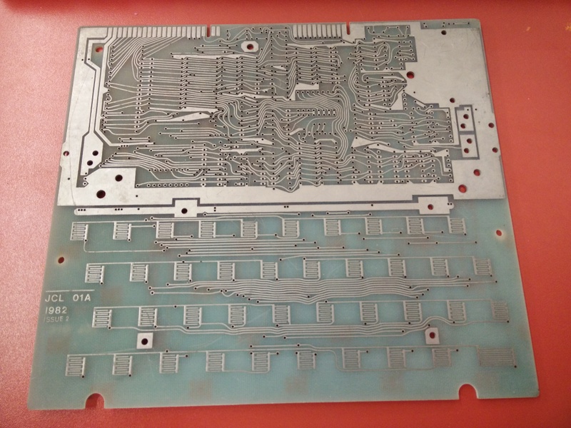
The PCB itself was typical of those from 1982. All the tracks had been laid out by hand, with different size pads (depending on the stencil they had to hand?), solder mask on the underside only and no silk screen. There was quite a big scratch on the underside, although this checked out to be ok, and the board was in otherwise pretty good condition. Unlike the ZX81 or Spectrum, it used standard off-the shelf components (Except the ROM – more on that later)
The Jupiter ACE has 3k of RAM, (1k user space and 2k video memory) uses 6 2114 ICs, which are pretty rare now. Luckily, John had a few of these spare. I had pretty much all the other components, with Nottingham Hackspace donating a couple of 74LS logic chips and EPROMS and a small order to RS for the remaining items. As a variation to the original, I decided to use chip sockets throughout – I didn’t need to be as penny-pinching as people were 30 years ago!

Getting hold of a definitive circuit diagram wasn’t particularly easy. Several schematics exist, along with high resolution photos of original models – however, they all contradict each other in some way or another. Most differences are fairly trivial, some are improvements and some, well, are just different. I mainly went for info from Jupter-Ace.co.uk Grant Searles website and instructions from a Hungarian rip-off of Grants info
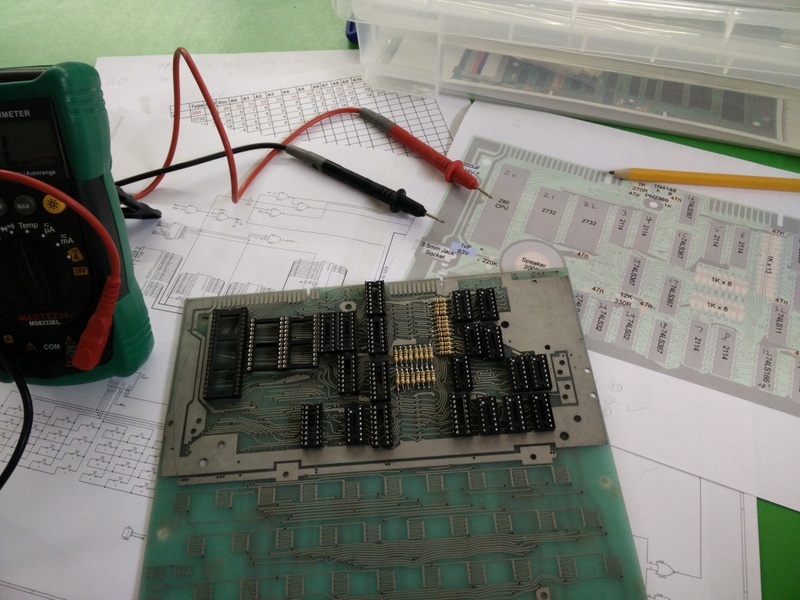
After some of the essential bits were put together, it was time for a few tests

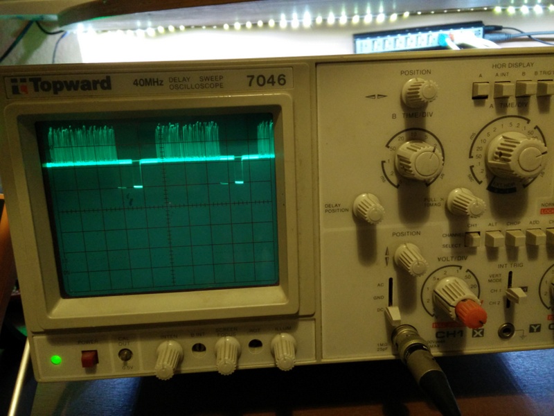
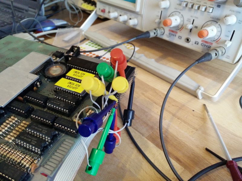
Even without any RAM installed, the video circuit could be tested. By looking at the output on a scope, it was clear that video signals were being generated. Below is a shot showing a couple of lines and the blanking signal. Things were looking good!
The original Jupiter ACE used an 8k ROM comprising of 2 2532 4k chips. These are nigh on impossible to get hold of these days, but have a very similar pinout to the industry standard 2732, although it requires a little modification to the PCB tracks. It seemed a shame to have to cut these, but there really is no neat way to get around this. The other problem I ran in to was that I could only find a copy of the ROM as a single 8k file. I assumed it was simply split in half with 0x0000 to 0x1FFF on one chip and 0x1000 to 0x1FFF on the other, but couldn’t find confirmation of this. (In case you’re using this blog for reference – that is, indeed, the case!)
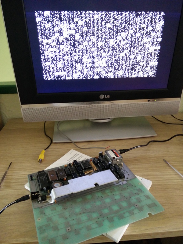
Things didn’t work though. The screen just filled with garbage! I wasn’t sure if this was a problem with the ROMs I’d burned, the memory, any of the old components I’d used, my soldering or anything else. After comparing signals with Johns fully functioning Jupiter ACE, it was tracked down to the clock to the CPU not being a strong enough signal to get through. This is amplified by a transistor with a couple of resistors which is one part of the circuit that’s different depending which source you look at. I fixed this with a small pot so I could tweak the gain to the sweet spot.
This gave me some success, although often only for a few seconds before the computer reset itself. Much head scratching and logic analysing went on before this was diagnosed as a power supply issue. I’d been using a ZX81 power supply, and this is rectified down to 5v by a 7805 onboard the ACE. If I bypassed this and just fed a regulated 5v from a USB adapter in, it worked fine!

The modulated UHF signal looked ok on my TV, but I hooked up a simple composite interface, and this gives a much sharper picture. So far, so good…

As you can see, the keyboard is made up of PCB tracks that need a metalised rubber keyboard to make the circuit. Original Jupiter ACE ones are not available, and I don’t think I could put anything together that would both work and do the old thing justice. So, instead, I’m working on something to offload the keyboard function to a regular PC keyboard. Look for more posts on this as it gets done.