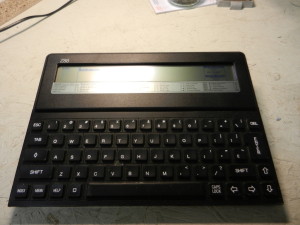
As mentioned in a couple of other posts here, the Z88 is a great machine. It comes with 32k of RAM, although this can be expanded with plug in cartridges. An alternative, however, is to replace the internal 32k with something larger. This photo tutorial shows how you can expand the onboard memory to 512k.
This involves some pretty hardcore soldering, and is not recommended for your first soldering project. More importantly, there is some delicate unsoldering too, and if things go wrong, you’ve wrecked your Z88. You have been warned!
The first thing I should point out that I didn’t come up with this modification myself. There is an article (long since lost) that has been reproduced on several websites that describes what to do. It’s quite slim when it comes to photos or clear diagrams though, so basically what I’ve done is just follow instructions, take photographs and write up my experience.
For a copy of the original article, see this link;
http://www.worldofspectrum.org/z88forever/memupgrd.htm
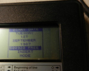
To start with, check the free memory on your Z88. (There’s technically no reason why you need to do this, but it’ll give you that nice warm fuzzy feeling when you do this again after the upgrade!)
To see this, push Diamond > E > M > F
I had already done a hard reset (hence the date back to 1987), but 20992 bytes free is about 20K
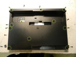
There are 11 screws (2 hidden under rubber feet and one under the serial number). They’re all the same size, so no need to worry about remembering which one came from where.
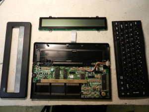
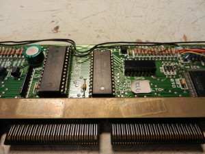
With all the screws removed the bezel, screen and keyboard lift off of the top. The ribbon cables to the screen and keyboard pull out, but be careful not to kink or fold them.
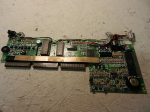
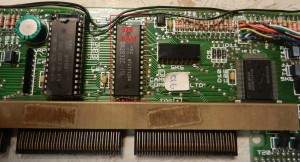
Unclip the battery connectors from the case and lift the motherboard out
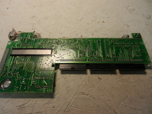
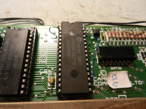
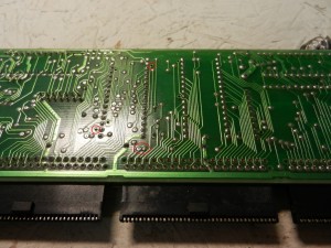
The underside of the motherboard
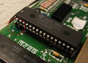
The chip highlighted is a 28 pin 32k RAM chip. This needs to be carefully removed.
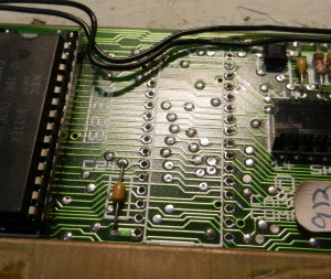
Note that the replacment chip is a 32 pin chip, so you will also need to unsolder the 4 filled holes above.

Solder in a low profile 32 pin socket.
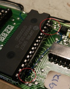
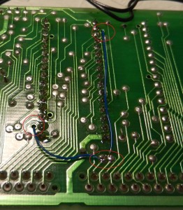
Before inserting the chip, bend out pin 1 (top left hand pin) and pin 30 (third one down on the right). Note where the holes going through the board are marked. Feed insulated wire through the holes and solder one end to pin 30…
… and another one end to pin 1
The other ends goes to two pads by the middle expansion connector. Do not insert the wire too far in to this hole.
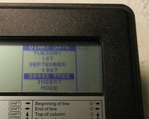
Reassembly is reverse of disassembly. When done, check the free memory (diamons > E > M > F) for that nice warm fuzzy feeling in a job well done!