A decent multimeter is great, but there’s times when you just want to have a quick check to see what signals are high, low or neither. A logic probe is ideal for this, but the cheap ones are about £15+, so I decided to build my own. For less than a quid!

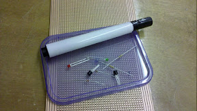
Components
2n2222
2n3904
10K resistor x 2
220R resistor x 2
Red LED
Green LED
Small bit of Veroboard
Safety pin or paper clip
Marker pen
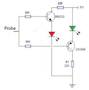
The circuit is quite strait forward, and with very few components is easy enough to build on stripboard;
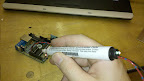
To build it, the innards of the pen are removed, and 3 small holes drilled in the end cap for the red and green LEDs, and the two power leads.

The pen case I used was wide enough for stripboard 4 strips wide which made the assembly easily enough, although with careful positioning 3 or possibly 2 strips would probably be possible.
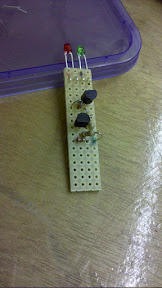
A couple of inter-board connecting wires and the positive, negative and probe lead soldered on and it’s ready to go inside the cap.
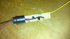
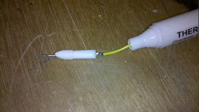
The probe lead needs to be plenty long enough to thread through the tip of the pen, and can then be cut down short enough to solder to the probe itself. The probe was made from the pin part of a safety pin and poked through the felt tip of the pen.
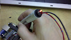
When connected to +5V and ground the two LEDs will faintly glow (Should be quite even, although with this one, the green was slightly brighter than the red)
When the tip of the probe connects to a high signal the red LED glows brightly;
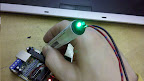
And when the tip goes to earth the green LED glows brightly;
If both LEDS glow brightly or flash between them, then the signal is pulsing.
For more photos, see the Picasa album here