The mounting of the LED matrix has probably caused me the biggest turmoil so far on the Retro Challenge. First, I was going to design a custom PCB for them, but I missed the window of opportunity to get it manufactured at a reasonable price. So, for simplicity, I decided to use breadboard until I realised this wasn’t simple with that amount of wires. So, I went back to PCB design preparing to take the financial hit. However, it proved impossible to get the tracks to fit, so this idea went in the bin again. Back to breadboard, I bought a load of jumper cables, and started expanding on what I started earlier. For the driver chips it was ok. For the matrices themselves though, I came across a show stopper; The width of it is so wide that in the breadboard there are 2 free tie points on one side but just 1 on the other. Getting a data bus down all of them was not going to be possible :-(
So, I had a rummage through some vintage Veroboard and found a Euro-card sized board with chip layout tracks. It would only fit 5 modules side by side, but I was prepared to make that sacrifice. I also had some 40 pin female sockets, so that made life even easier!
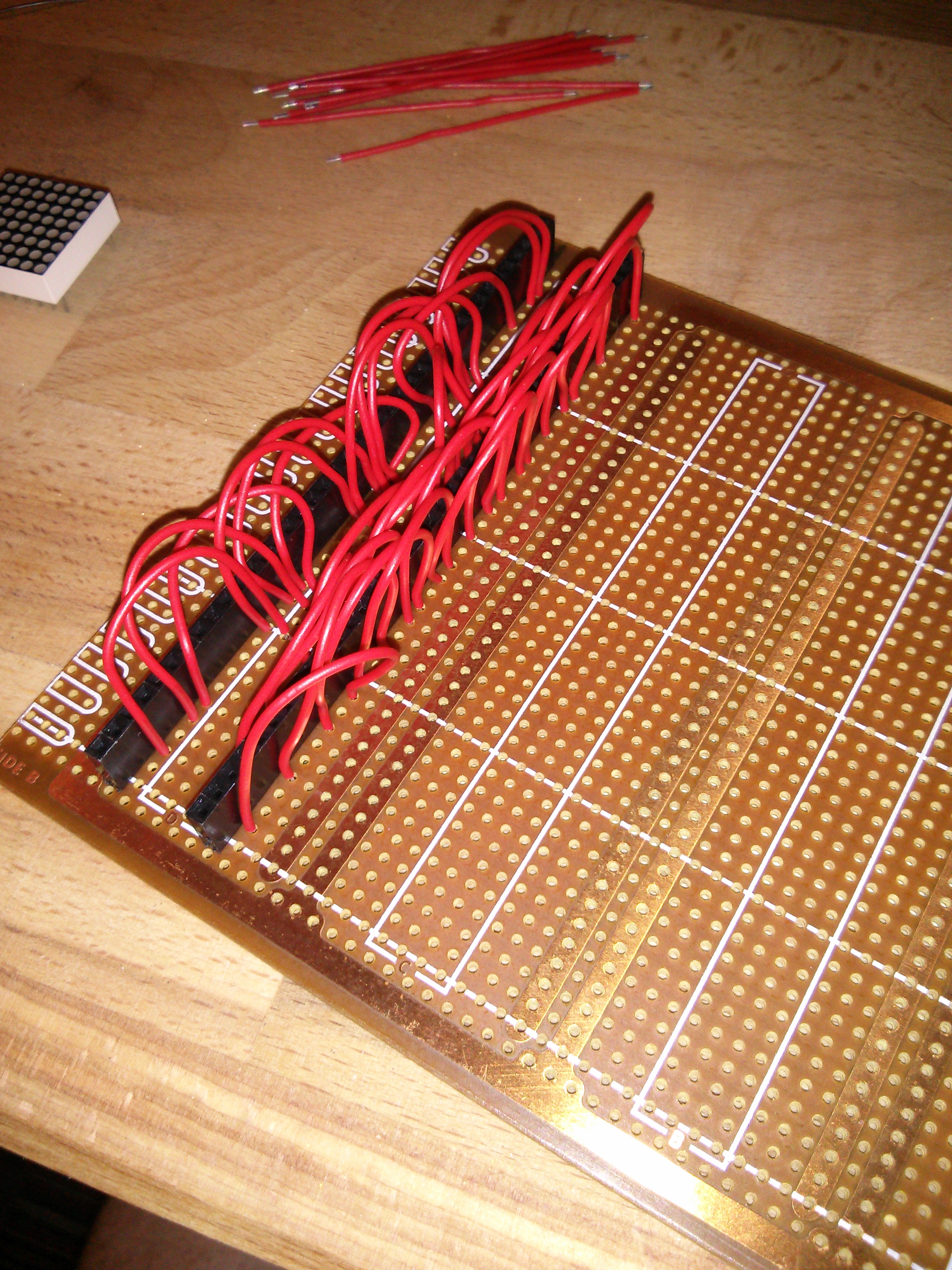
All the Y axis data bus cables went in fine. I was running out of solder though, but had just enough left for the chip sockets
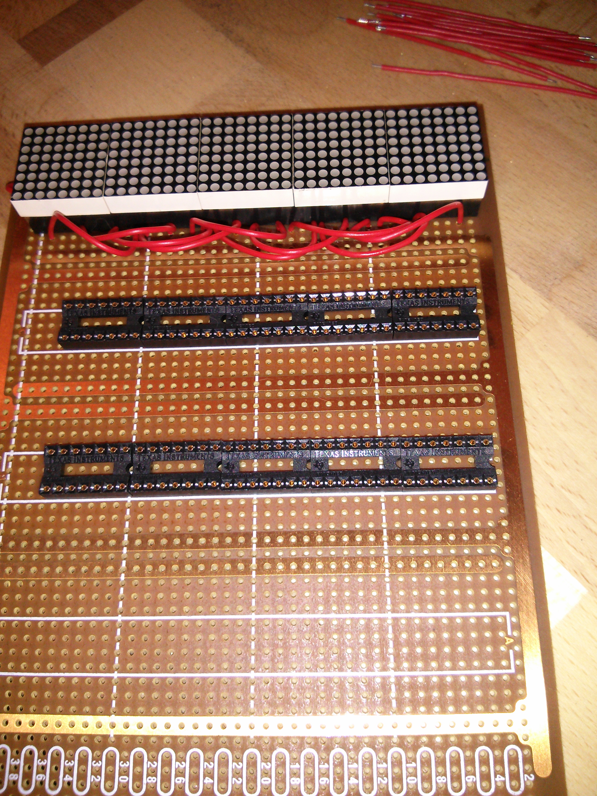
I didn’t have the appropriately sized 20 pin sockets, but I did have plenty of 14 pins ones… so I’ll just have to be careful in marking where one chip ends and the next one starts.
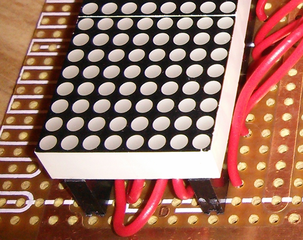
There’s still a lot more wires (25 actually) to connect under the LEDs, but the headers are quite tall so there should be enough room to hide them away.
Hopefully I’ll be able to complete this at the weekend, in time for the other PCBs to arrive.